No products in the cart.
TB6600 CNC Stepper Motor Driver Controller 4A 9~42V TTL 16 Micro-Step
KSh1,350.00
In stock
SKU: 10782 Categories: Motor driver module, Relays, Motors, Motor drivers, Pumps & Valves Tag: Stepper motor driver
Description
Driver board features:
* Highly integrated and highly reliable
* Interface signals using high-speed optocoupler isolation
* Up to 4.5A high current output
* The maximum input voltage DC42V
* Overvoltage. Undervoltage. Overcurrent alarm protection
* Automatic half-flow, reduce energy consumption
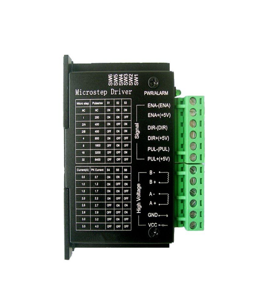
Terminal Definition Description
Signal input
⑴ CP +: positive pulse signal input.
⑵CP-: pulse signal input negative terminal.
⑶DIR +: positive and negative motor control positive end.
⑷ DIR-: motor is positive, negative control negative end.
⑸ EN +: motor offline control is positive.
⑹EN-: Motor offline control negative terminal.
Motor winding connection:
⑴ A +: Connect motor winding A + phase.
⑵ A-: Connect the motor winding A-phase.
⑶B +: connect the motor winding B + phase.
⑷ B-: connecting the motor winding B-phase.
Operating voltage connection:
⑴VCC: DC power supply positive (Note: 10V ⑵GND: negative DC power supply.
Signal input optocoupler isolation connection
Input signal interface has two kinds of connection: the user can use common anode connection or common cathode connection.
1. Common anode connection: connect CP +, DIR + and EN + to the control system respectively. If the power supply is + 5V, it can be connected directly. If the power supply is greater than + 5V, an additional current limiting resistor R , To ensure that the internal optical drive to provide drive 8-15mA drive current. Pulse input signal through the CP-access; At this time, DIR-, EN- in the low-effective.
2. Common Cathode Connection: Connect CP-, DIR- and EN- to the ground of control system (SGND, isolated from power supply) respectively; + 5V pulse input signal is added through CP +; at this moment, DIR +, EN + High effective. The current-limiting resistor R is connected in the same way as the common-anode connection.
Note: EN terminal can not be connected, EN is valid when the motor rotor is free (offline), then you can manually rotate the motor shaft, do the adjustment for you. After the manual adjustment is completed, set EN to inactive to continue the automatic control.
Subdivision setting
The number of subdivisions is set by the dial switch selection on the engine board, which is set according to the data of the subdivision selection table (preferably set in case of power failure). Subdivision Stepper motor step angle according to the following method: Step angle = motor inherent step angle / subdivision. For example, a stepping motor with an inherent step angle of 3.6 ° has a step angle of 3.6 ° / 16 = 0.225°
Drive board subdivision module DIP switch 1, 2, 3, respectively, corresponding to M1, M2, M3.
Subdivision table as shown:
Drive board current module DIP switch 4,5,6, respectively, corresponding to M4, M5, M6.
Related products
Relays, Motors, Motor drivers, Pumps & Valves
L293D Motor Drive Expansion Shield Board Module/H BRIDGE For Arduino
KSh1,000.00
Relays, Motors, Motor drivers, Pumps & Valves
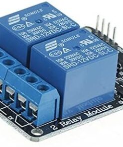
5V 2 Two Channel Relay Module DC 5V + Optocoupler For Arduino PIC ARM AVR DSP
KSh350.00
Relays, Motors, Motor drivers, Pumps & Valves
KSh550.00
Relays, Motors, Motor drivers, Pumps & Valves
KSh1,000.00
Relays, Motors, Motor drivers, Pumps & Valves
KSh1,200.00
Relays, Motors, Motor drivers, Pumps & Valves
KSh200.00


